
AEROPROPSIM / RESEARCH DEMONSTRATION
NASA X-57 Maxwell
Distributed propulsion.
From propeller loading to powered-wing response. Exploring aircraft-scale interactions through rapid aerodynamic modelling.
A complete reference-aircraft visualisation accompanies a completed, twelve-propeller main-wing study. This is a research demonstration using NASA’s public X-57 configuration, developed independently by SanHang without NASA affiliation or endorsement.
01 / AIRCRAFT & PROPULSION WAKES
One aircraft.
Many interacting wakes.
Full reference geometry.
Explicit modelling boundaries.
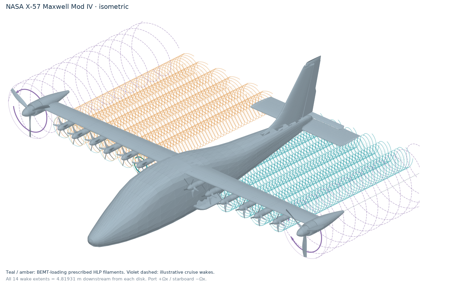
- Solved propulsion
- 12 HLPsIndependently computed blade-element loads
- Visual reference
- 14 installationsTwelve high-lift + two cruise propellers
- Displayed wake extent
- 4.82 mHalf of the 9.639 m reference wingspan
Aircraft geometry. Main-wing aerodynamics.
The native aircraft display includes the fuselage, tails, nacelles and propellers. Calculated forces cover the clean main wing coupled one way to twelve high-lift propellers. The drawn helices are prescribed filament geometry; reported wing loads use a separate radial BEMT slipstream field.
The proposed all-fourteen-propellers-active case remains under development. Source-matched cruise blade sections, root treatment and the low-speed pitch schedule are unresolved. This proposed scenario should not be read as the X-57’s normal operating configuration or an achieved fourteen-propeller aerodynamic solution.
02 / SPANWISE WING LOADING
See where
the loading changes.
Unpowered baseline.
Twelve high-lift propellers operating.
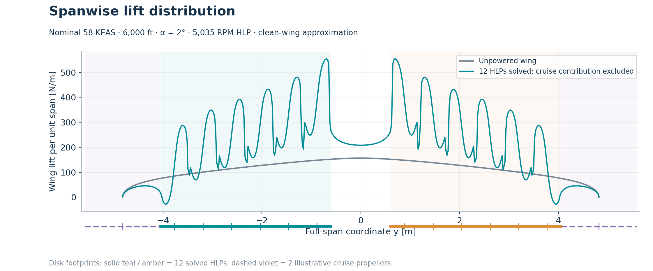
| Configuration | Wing CL | Wing lift [N] | HLP shaft power [kW] |
|---|---|---|---|
| Unpowered | 0.320967 | 1,087.254 | 0 |
| Twelve HLPs | 0.619789 | 2,099.495 | 162.699 |
Lift is in the aircraft geometry-z direction; rotor thrust is separate. These are exploratory model outputs, not measured aircraft performance. The predicted 13.558 kW per HLP exceeds the nominal 10.5 kW motor specification in NASA’s overview; no motor power limit is imposed, so this is not a demonstrated feasible flight point.
03 / PANEL LOADING
A view across
the wing surface.
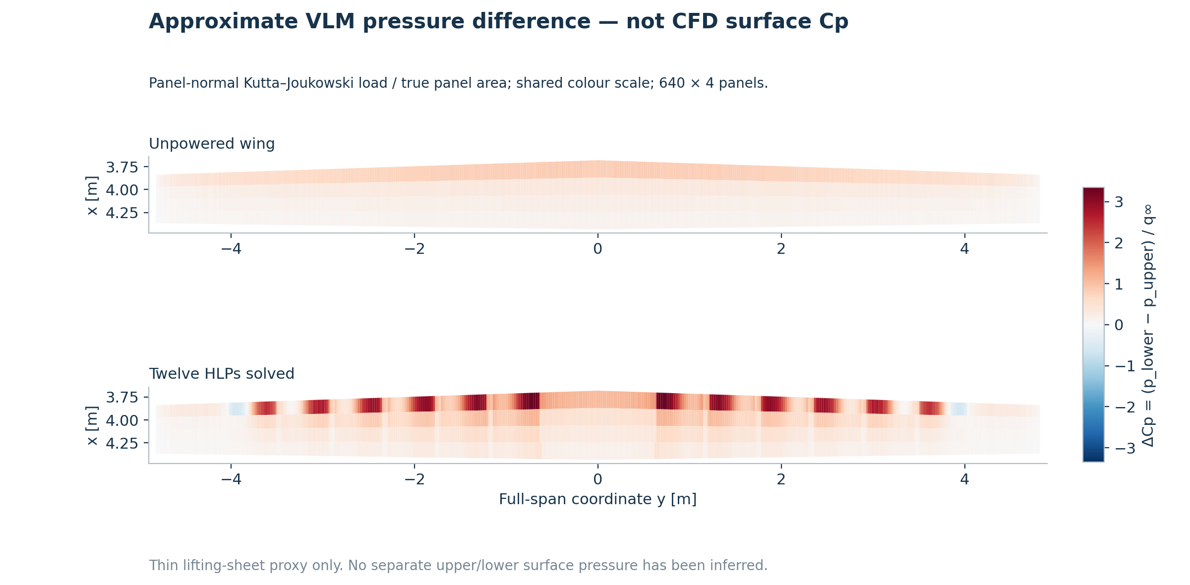
Approximate VLM pressure difference.
Not full CFD surface pressure.
04 / TECHNICAL RECORD
Conditions, methods
and measured cost.
- Configuration
- NASA Mod IV reference geometry; twelve solved high-lift propellers; two cruise propellers displayed only. Clean main-wing force model.
- Operating condition
- Nominal 58 KEAS; true airspeed 32.67456 m/s; altitude 6,000 ft; density 1.024573 kg/m³; angle of attack 2°. Exploratory reference condition.
- Propeller state
- High-lift propellers: 5,035 RPM, five blades, 0.28796 m radius. Cruise display reference: 1,540 RPM; no cruise thrust, torque or power prediction.
- Aerodynamic methods
- Axial blade-element momentum theory (BEMT) with retained local XFOIL section polars; natural transition and explicit alpha extension. Horseshoe vortex-lattice method (VLM) for the main wing.
- Wake & coupling
- One-way, superposed radial BEMT slipstream fields. Fixed-radius prescribed model; no contraction, deformation, reciprocal wing feedback or mutual rotor loading. The analytical field is not cut off at the visual wake endpoint.
- Spatial discretisation
- 640 spanwise strips × 4 chordwise horseshoe rows; 80 BEMT radial elements per HLP. Display helices use 40 remapped radial cells and 432 segments per filament; selected filaments are drawn for clarity.
- Calculated quantities
- Main-wing lift, CL, circulation and spanwise loading; HLP thrust, torque and shaft power; induced velocity; approximate panel-normal pressure difference.
- Physical simulation time
- Steady calculation. No time-marched physical duration is defined. Displayed wake length does not represent a transient simulation record.
- Computational wall-clock time
- Powered solver median: 6.849 s across three solves (6.768–6.911 s). The primary run took 7.111 s including input preparation and numerical export. Plot and rendering time is excluded.
- Recorded hardware
- Apple M3 Pro, 18 GB memory, retained workspace hardware record. Sequential cases with single-thread numerical libraries requested; warm OS caches were not controlled. Timings are case-specific.
Verification & remaining uncertainty
The archived checks cover rotor convergence, force/coefficient identities, pressure-load closure, mirrored loading and selected discretisation and input sensitivities. They establish numerical consistency within the chosen model.
- 640 versus 960 span strips changes integrated wing CL by approximately 0.37%; span refinement is nonmonotonic and local loading is more sensitive.
- Changing the transition assumption changes powered CL by approximately −5.8%. This is a sensitivity result, not a confidence interval.
- Wing camber, deployed flaps, viscous/stall physics, body interference and loaded-blade geometry remain unresolved. A matched full-aircraft physical validation has not been established.
The separate PROWIM experimental comparison tests propeller–wing interaction modelling in its own benchmark conditions. Its validation scope does not transfer automatically to the X-57 case.
05 / SOURCES & DATA
A traceable
research demonstration.
Figures and numerical results: AeroPropSim, X57-DEMO-01, 23 October 2026. Aircraft reference geometry: NASA X-57 Maxwell. The rendering uses the native public reference model with its documented component selection; all aerodynamic overlays and research plots are AeroPropSim outputs.
- NASA: X-57 Maxwell public geometry reference
- NASA/TM-20230010662: landing-configuration computational analysis Reference conditions only. NASA’s deployed-flap CFD configuration differs from this clean-wing model.